


| Photocell Type | Photoresistor |
| Brand | Quick Sense |
| Ambient Light | < 10-100 LUX |
| Model Number | RBL Photocell for Riello Industrial Burners |
| Application | Light Sensing |
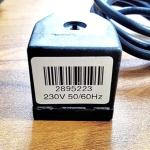
| Operating Voltage | 220-250 V |
| Frequency | 50 Hz |
| Rated Current | 10 A |
| Working Temperature | -40 to 125 Deg C |
Minimum order quantity: 1 Piece
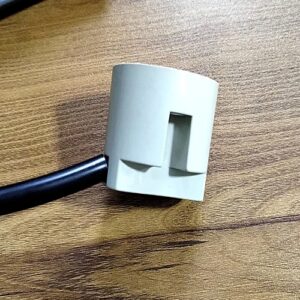
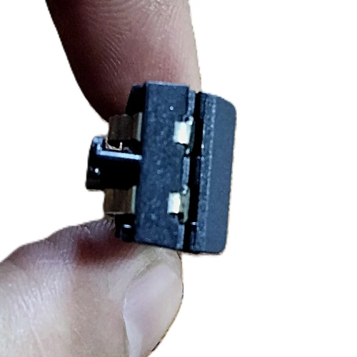
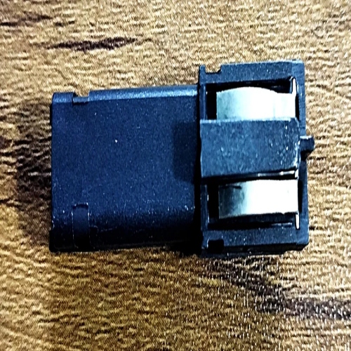
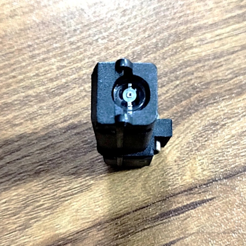
2. Photocell Type & Construction
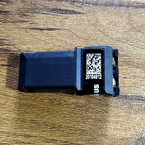
3. Part Numbers & Compatibility
4. Electrical & Connection Specs
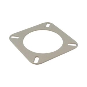
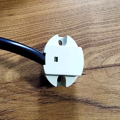
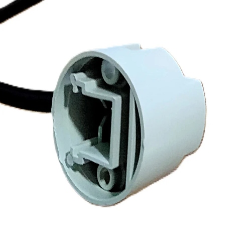
5. Installation & Maintenance Mounting
Cleaning & Inspection
Replacement Procedure
Troubleshooting
Summary Table
| Feature | Specification |
|---|---|
| Type | RBL reflex‑type burner flame sensor |
| Voltage | 230 V, 50 Hz AC |
| Interface | “FR” terminal on RMO control box |
| Maintenance | Clean glass; inspect gasket; check wiring |
| Troubleshooting | Continuity <1 kΩ, no flame → lockout check |